Best Regards
----------------------------------------------------------------------
LU Yang 陆洋
传送与接入研究部
工业和信息化部电信研究院通信标准研究所
(原工业和信息化部电信传输研究所)
Research Institute of Telecommunications Transmission (RITT),
China Academy of Telecom. Research (CATR), MIIT
TEL: 86-10-62300117, 86-18510550580, 13661386633
E-mail: luyang@xxxxxxx , luyang_ritt@xxxxxxx
----------------------------------------------------------------------
From: Glen Kramer
[mailto:gkramer@xxxxxxxxxxxx]
Sent: Thursday, January 22, 2015 5:38
PM
To: Marek Hajduczenia;
STDS-1904-2-TF@xxxxxxxxxxxxxxxxx
Subject: RE: [1904.2 TF] UMT
Discovery protocol
From: Marek Hajduczenia
[mailto:marek.hajduczenia@xxxxxxxxx]
Sent: Thursday, January 22, 2015 12:07 PM
To: Glen Kramer;
STDS-1904-2-TF@xxxxxxxxxxxxxxxxx
Subject:
RE: [1904.2 TF] UMT Discovery protocol
Glen,
Some feedback on your questions
/ comments:
1)
Some operators
explicitly filter any frames in upstream transmitted with multicast address(es).
That is done to prevent users from sourcing multicast content from their home
and causing overload on the routing plane. To make UMT work across edges of L2
domains, we will need to define specific forwarding rules for broadcast UMT
traffic, but I would suggest we avoid multicast addressing. Broadcast we control
and know how to handle today (ARPs, DHCP, etc. ) but multicast would require
specific new ACL rules on the edge to assure that such frames are not dropped.
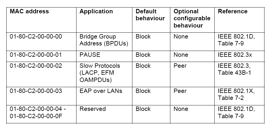
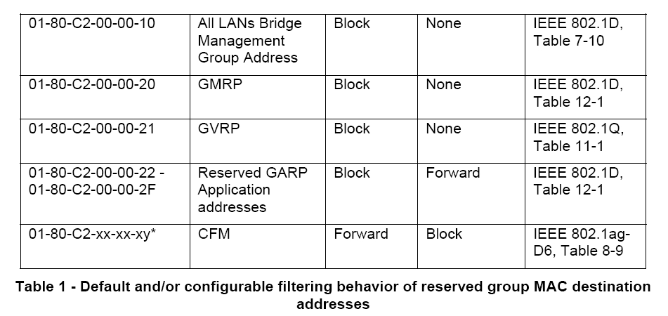
GK: We also use well known multicast
addresses for all MAC Control frames and for OAM frames. Here is the listing of
all the assignments: http://standards.ieee.org/develop/regauth/grpmac/public.html
. Seems all L2 control protocols get L2 group address different from
broadcast. I saw that 1905.1 also reserved an address for their control
protocol: 01-80-C2-00-00-13 Transmission of IEEE 1905.1 control packets.
[mh1022] These are link local
messages only, i.e., they are not transmitted across multiple L2 hops. I am not
sure how legacy devices would behave with a new multicast address that is
currently on reserved list – I’d assume they would just drop such frames, not
knowing what to do with them.
GK: Not sure I agree. A protocol
that uses each group address determines whether it is link-local or not. MAC
Control and OAM consume the frames and don’t forward them. That makes it
link-local. If they don’t consume a frame, that frame is forwarded. Most
of the addresses listed on RegAuth website are not link local.
[mh1022-1] You’re right. There
is still, though, the concern of these belonging to the group of multicast
addresses, which are typically not forwarded across access links.
2)
I am not sure a new
Ethertype is required. I would use a subtype (say, 0x00) for control traffic and
keep it within the same Ether domain. Let’s not create too many protocols – it
would be a hard sale to get two Ethertypes, especially when the volume of
control traffic is not that extensive here outside of discovery phrase.
GK: I would
agree.
3)
As indicated in 1),
I believe we will need to flood only ports designated as UMT ports. Otherwise,
UMT will leak into whole L2 domains, creating potentially broadcast storms in
multiple locations. A really bad thing to have, and we would need to keep
running spanning trees to prevent the occurrence of loops. Today, we have
redundant links, but they are controlled at IP+MPLS level for traffic
engineering, but from L2 perspective they might create loops. It is a complex
topic once you leave the access and move into metro and core networks.
GK: A UMT-aware intermediate device
should forward this frame to only one port – toward its UMT Domain Controller
(assuming they themselves have already discovered the UMT Domain
Controller)
I assume a non-UMT-aware device has
to flood it to all ports except where the message arrived from. Are there other
possibilities?
[mh1022] Ah, that is the case of
flooding you are referring to. I assume then this flooding would be constrained
to within L2 broadcast domain and not traverse multiple L2 domains. In short, a
node would flood discovery message into its local L2 network, and then only
designate selected ports of UMT ports, depending on where the response comes
from (if any). Does that sound about right?
GK: L2 flooding is always
constrained to L2 Broadcast domain. The question is whether UMT Domain is the
same as L2 broadcast domain, or whether L2 Broadcast domain can be broken into
multiple UMT domains.
[mh1022-1] I believe we
discussed that at the meeting and conclusion was that UMT Domain can span
multiple L2 domains, right?
Slide 2 does not show CNU
discovery stage. I assume that UMT discovery is sent by FCU when a new CNU is
discovered. Is that a correct assumption? Or rather is the initial 3 message
sequence intended to register FCU as an UMT node with the controller and enable
for UMT transport for CNUs that are discovered and register later on?
GK: The second case. In this
diagram, FCU is a UMT-aware device and registers with the UMT Domain Controller
first. Then, when CNU tries to register, the FCU just forwards the UMT-QUERY
towards the UMT Domain Controller, which it already knows. The diagram shows
establishment of two tunnels: one from server-side end point to the FCU, another
is from server-side end point to the CNU.
[mh1022] Can we add dashed boxes
around individual phases for simpler understanding?
GK: Done. The updated version is
posted at http://www.ieee1904.org/2/meeting_archive/2015/02/tf2_1502_kramer_3a.pdf
[mh1022-1] Thank you, that looks
much better IMO.
Marek
From: Glen Kramer [mailto:gkramer@xxxxxxxxxxxx]
Sent: Wednesday, December 17, 2014 6:01 PM
To: STDS-1904-2-TF@xxxxxxxxxxxxxxxxx
Subject:
[1904.2 TF] UMT Discovery protocol
Dear Colleagues,
At the last meeting, we have discussed the initial version of
the UMT discovery protocol (v1) and produced an updated version (v2) as a result
of this discussion (see http://www.ieee1904.org/2/meeting_archive/2014/12/tf2_1412_kramer_3.pdf
)
Attached here is version 3 (which is just a cleaned up
version 2) with some additional questions that need to be
clarified.
Also, at the last meeting, I took an action item to “show a
protocol diagram simplified for EPoC”.
The simplification would come from the fact that the
Client-Side End Point (CSEP) and the management client are part of the same
device (CNU or FCU), and the Server-Side End Point (SSEP) and UMT Domain
Controller are part of the OLT.
The second page of the attached document shows this
simplified EPOC use case.
Please, review and let us further discuss on the
reflector.
Glen